Command Pattern Tutorial
Welcome to this tutorial on the Gang of Four (GoF) command design pattern. Throughout this guide, we will help you understand the definition and application of the command pattern in your software projects. By following our step-by-step instructions, you will learn how to create a UML class diagram for the command pattern and save it as a design pattern file that can be reused in the future. Whether you are an experienced developer or just starting, this tutorial will provide you with valuable insights into how the command pattern can be used to improve your code.
What is Command Design Pattern?
The Command Design Pattern is a software design pattern that encapsulates a request as an object, thereby allowing for the parameterization of clients with different requests, and for the support of undoable operations. In this pattern, a command object is created that contains all the information necessary to perform a specific action, including the method to call, the arguments to pass, and the receiver that will perform the action.
The purpose of the Command pattern is to decouple the object that invokes the operation from the one that knows how to perform it. This allows the invoker object to be easily parameterized with different commands, and allows for the separation of concerns between the invoker and the receiver of the command.
The Command pattern is commonly used in object-oriented programming languages such as Java and C++, where it is used to implement menu systems, undo/redo functionality, and other software applications that require the encapsulation of requests as objects.
The Command pattern is an important concept for any programmer to understand, as it provides a simple and flexible way to implement complex functionality, and allows for the easy extension of the system by adding new commands.
Modeling Design Pattern with Class Diagram
- Create a new project Design Patterns.
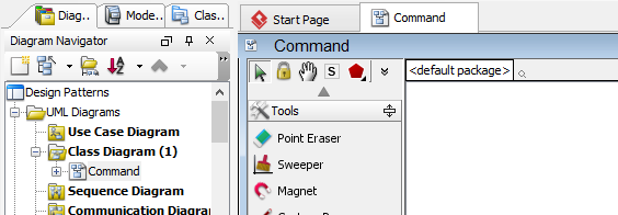
- Create a class diagram Command.
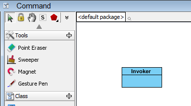
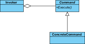
- Select Class from diagram toolbar. Click on the diagram to create a class. Name it as Invoker.
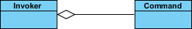
- Move the mouse cursor over the Invoker class, and drag out Aggregation > Class to create an associated class Command.
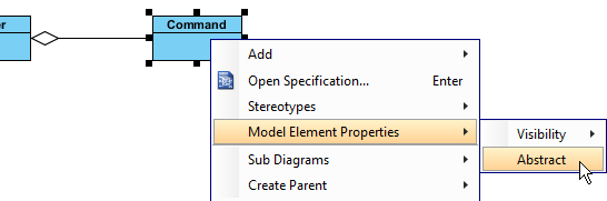
- Right-click on Command, and select Model Element Properties > Abstract to set it as abstract.
- Right-click on Command class, and select Add > Operation from the popup menu.
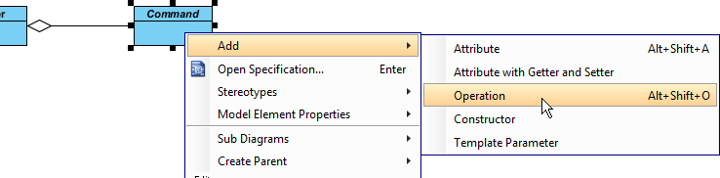
- Name the operation Execute().
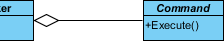
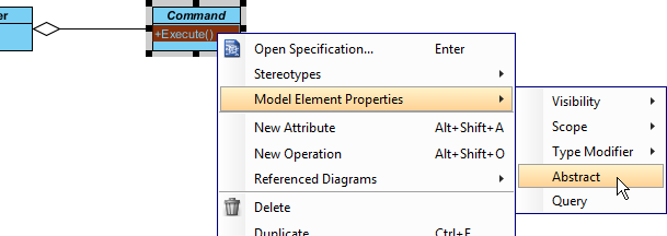
- Right-click on Execute, and select Model Element Properties > Abstract to set it as abstract.
- Move the mouse cursor over the Command class, and drag out Generalization > Class to create subclasses ConcreteCommand.
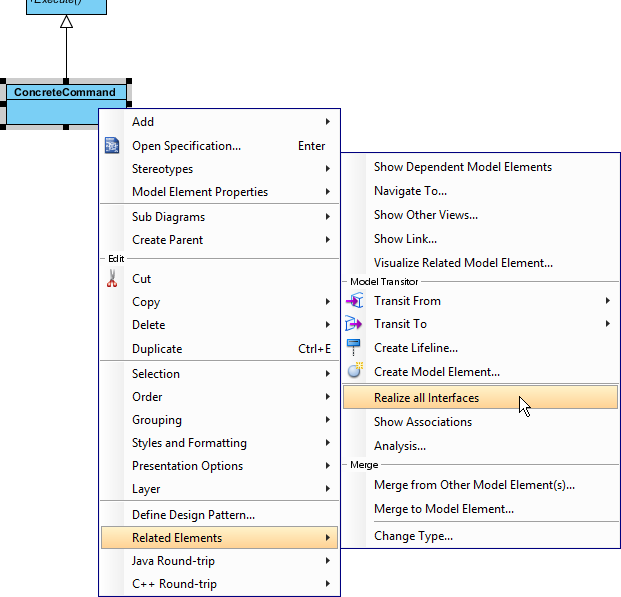
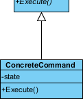
- We need make the concrete commands inherit operations from the command class. Right-click on ConcreteCommand and select Related Elements > Realize all Interfaces from the popup menu.
- Right-click on the ConcreteCommand class, and select Add > Attribute from the popup menu. Enter state as attribute name.
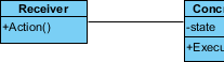
- Move the mouse cursor over the ConcreteCommand class, and drag out Association > Class to create an associated class Receiver.
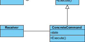
- Right-click on the Receiver class, and select Add > Operation from the popup menu. Enter Action as operation name.
- Create a Client class near the Receiver class.
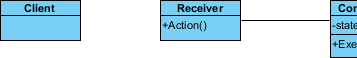
- Move the mouse cursor over the Client class, and drag out Association > Class to create an associated class Receiver.
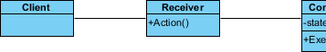
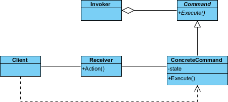
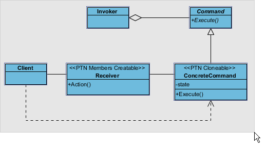
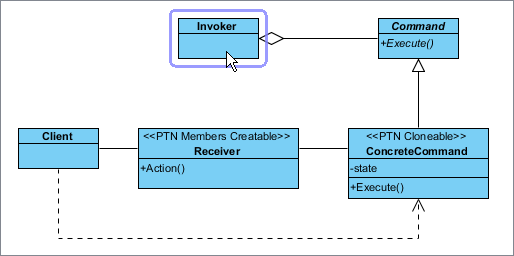
- Move the mouse cursor over the Client class, and drag out Dependency > Class to create an associated class ConcreteCommand. Up to now, the diagram becomes:
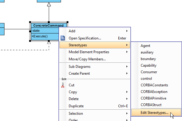
- In practice, there may be multiple concrete handlers. To represent this, stereotypes the class ConcreteCommand as PTN Cloneable. Right-click on ConcreteCommand and select Stereotypes > Stereotypes… from the popup menu.
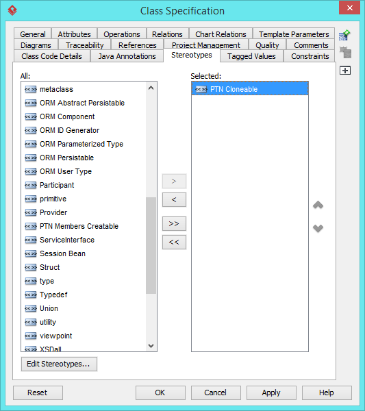
- In the Stereotypes tab of the Class Specification dialog box, select PTN Cloneable and click > to assign it to ConcreteCommand class. Click OK to confirm.
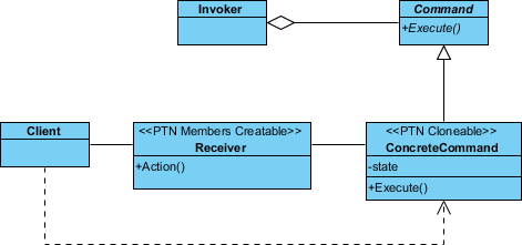
- There may be multiple actions that the receiver can perform. To represent this, stereotype the class Receiver as PTN Members Creatable. Up to now, the diagram becomes:
Saving the Defining Pattern
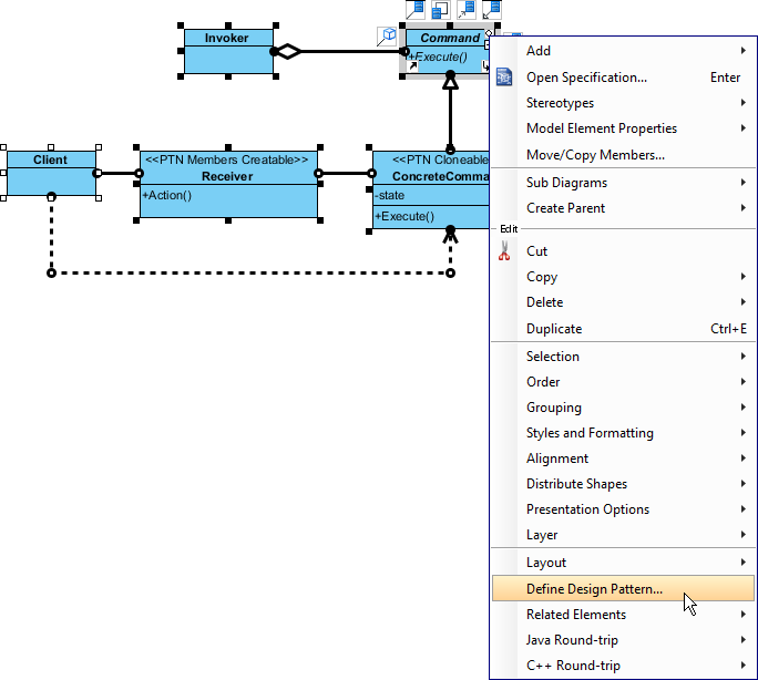
- Select all classes on the class diagram.
- Right-click on the selection and select Define Design Pattern… from the popup menu.
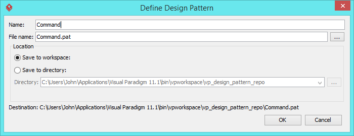
- In the Define Design Pattern dialog box, specify the pattern name Command. Keep the file name as is. Click OK to proceed.
Applying Design Pattern on Class Diagram
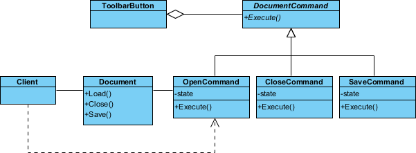
In this section, we are going to apply the command pattern in modeling a document editor.
- Create a new project Document Editor.
- Create a class diagram Domain Model.
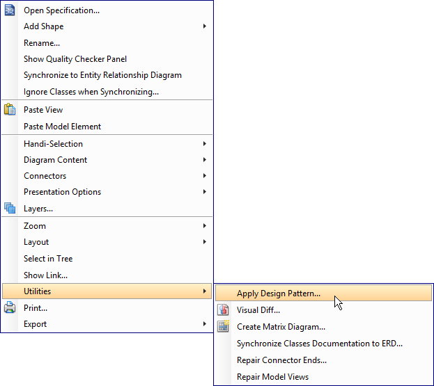
- Right-click on the class diagram and select Utilities > Apply Design Pattern… from the popup menu.
- In the Design Pattern dialog box, select Command from the list of patterns.
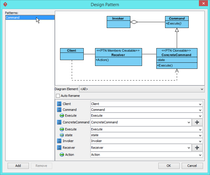
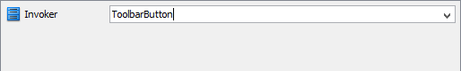
- Select Invoker in overview.
- At the bottom pane, rename Invoker to ToolbarButton.
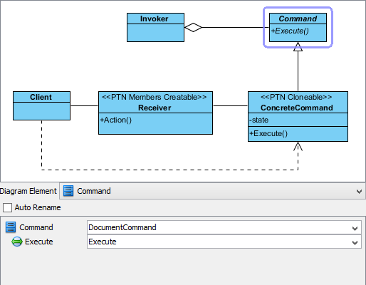
- Select Command in overview. At the bottom pane, rename Command to DocumentCommand.
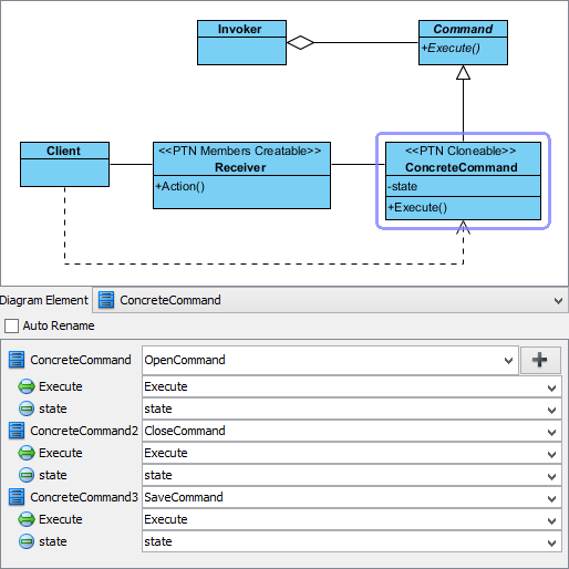
- Select ConcreteCommand in overview. At the bottom pane, rename ConcreteCommand to OpenCommand.
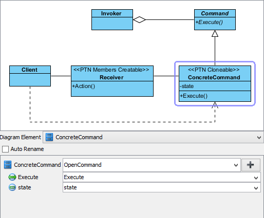
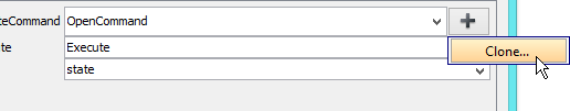
- We need 2 more concrete commands for closing and saving a document. Press on the + button and select Clone… from the popup menu.
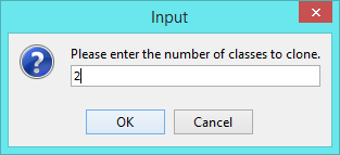
- Enter 2 to be the number of classes to clone.
- Rename ConcreteCommand2 to CloseCommand, ConcreteCommand3 to SaveCommand.
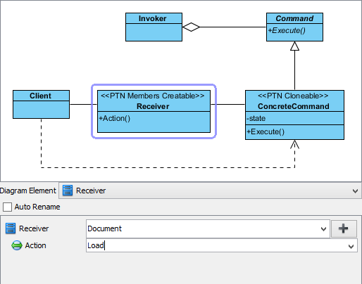
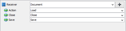
- Select Receiver in overview. At the bottom pane, rename Receiver to Document, and operation Action to Load.
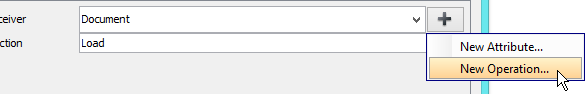
- Create more operations for closing and saving documents. Click on the + button and select New Operation… from the popup menu.
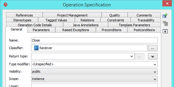
- In the Operation Specification, enter Close as name. Click OK to confirm.
- Repeat steps 13 and 14 to create operation Save.
- Click OK to apply the pattern to diagram.
- Tidy up the diagram. Here is the result: