Chain of Responsibility Pattern Tutorial
If you are interested in software design patterns, then you won’t want to miss this tutorial on the Gang of Four (GoF) chain of responsibility design pattern. Throughout this guide, we will show you how to define and apply the chain of responsibility pattern in your software projects. You will learn how to create a UML class diagram for the pattern and save it as a design pattern file that can be reused in the future. Whether you are a seasoned developer or just starting out, this tutorial will equip you with the skills and knowledge you need to successfully implement the chain of responsibility pattern in your code.
What is Chain of Responsibility Design Pattern?
The Chain of Responsibility Design Pattern is a software design pattern that allows a request to be passed through a series of handlers until one of them handles the request. In this pattern, each handler has a reference to the next handler in the chain, forming a chain of handlers.
The purpose of the Chain of Responsibility pattern is to decouple the sender of a request from its receiver, allowing multiple objects to handle the request without the sender having to know the exact receiver. This means that changes to the handlers can be made without affecting the sender, and new handlers can be added or removed from the chain without modifying the sender.
The Chain of Responsibility pattern is commonly used in object-oriented programming languages such as Java and C++, where it is used to implement event-driven systems, user interfaces, and other software applications that require multiple objects to handle requests in a flexible and extensible way.
The Chain of Responsibility pattern is an important concept for any programmer to understand, as it provides a simple and efficient way to decouple the sender of a request from its receiver, and allows for easy extension of the handling logic by adding or removing handlers from the chain.
Modeling Design Pattern with Class Diagram
- Create a new project Design Patterns.
- Create a class diagram Chain of Responsibility.
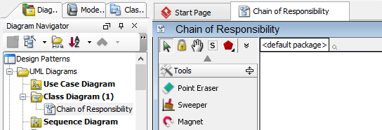
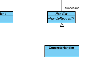
- Select Class from diagram toolbar. Click on the diagram to create a class. Name it as Client.
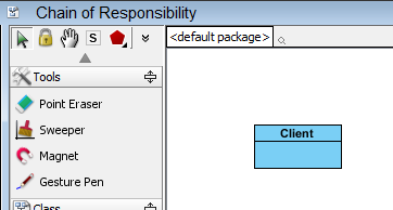
- Move the mouse cursor over the Client class, and drag out Association > Class to create an associated class Handler.

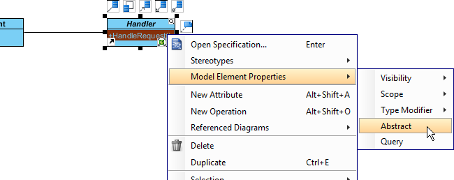
- Right-click on Handler, and select Model Element Properties > Abstract to set it as abstract.

- Right-click on Handler class, and select Add > Operation from the popup menu.

- Name the operation HandleRequest().
- Right-click on HandleRequest, and select Model Element Properties > Abstract to set it as abstract.
- Move the mouse cursor over the Handler class, and click on the resource icon Self Association to create a self association.

- Name the association end successor.

- Move the mouse cursor over the Handler class, and drag out Generalization > Class to create subclasses ConcreteHandler.
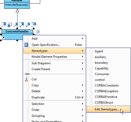
- In practice, there may be multiple concrete handlers. To represent this, stereotype the class ConcreteHandler as PTN Cloneable. Right-click on ConcreteHandler and select Stereotypes > Stereotype… from the popup menu.
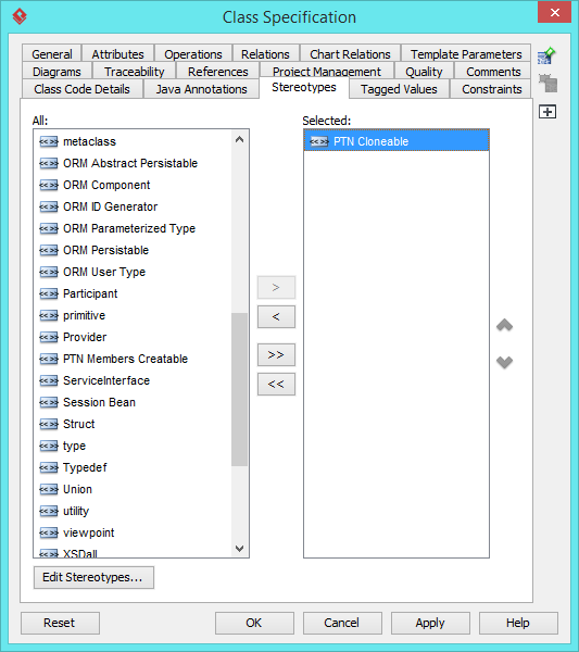
- In the Stereotypes tab of the Class Specification dialog box, select PTN Cloneable and click > to assign it to ConcreteHandler class. Click OK to confirm.
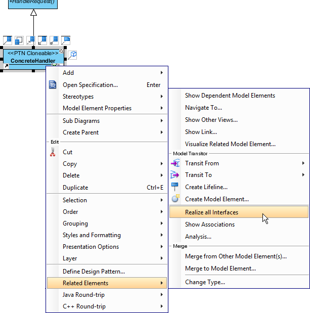
- We need make the concrete handlers inherit operations from the handle class. Right-click on ConcreteHandler and select Related Elements > Realize all Interfaces from the popup menu.
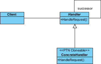
Up to now, the diagram should look like this:
Saving the Defining Pattern
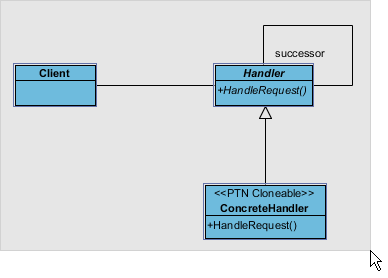
- Select all classes on the class diagram.
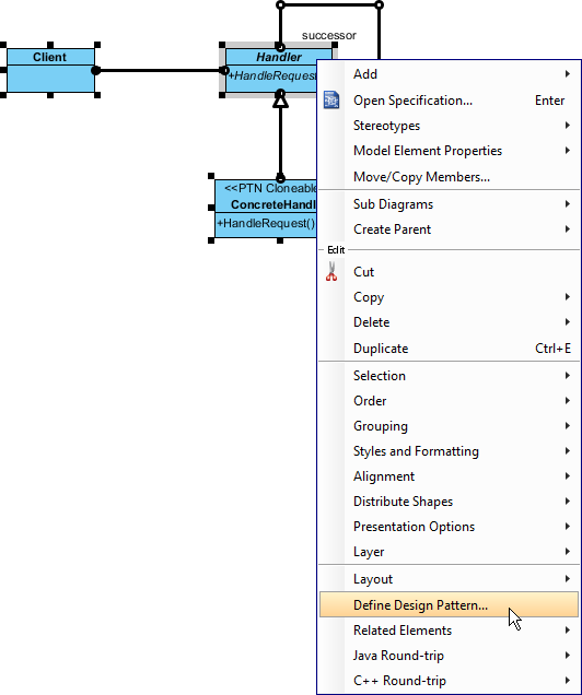
- Right-click on the selection and select Define Design Pattern… from the popup menu.
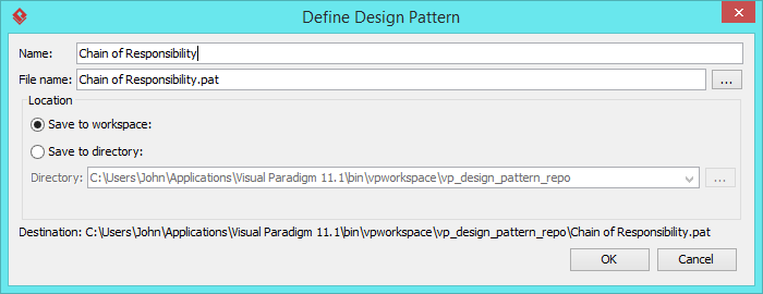
- In the Define Design Pattern dialog box, specify the pattern name Chain of Responsibility. Keep the file name as is. Click OK to proceed.
Applying Design Pattern on Class Diagram
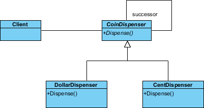
In this section, we are going to apply the chain of responsibility pattern in modeling a coin dispenser.
- Create a new project Coin Dispenser.
- Create a class diagram Domain Model.
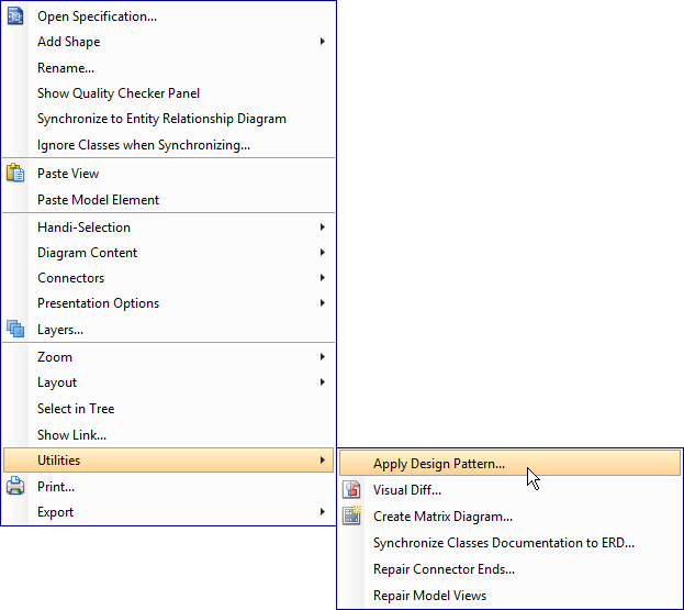
- Right-click on the class diagram and select Utilities > Apply Design Pattern… from the popup menu.
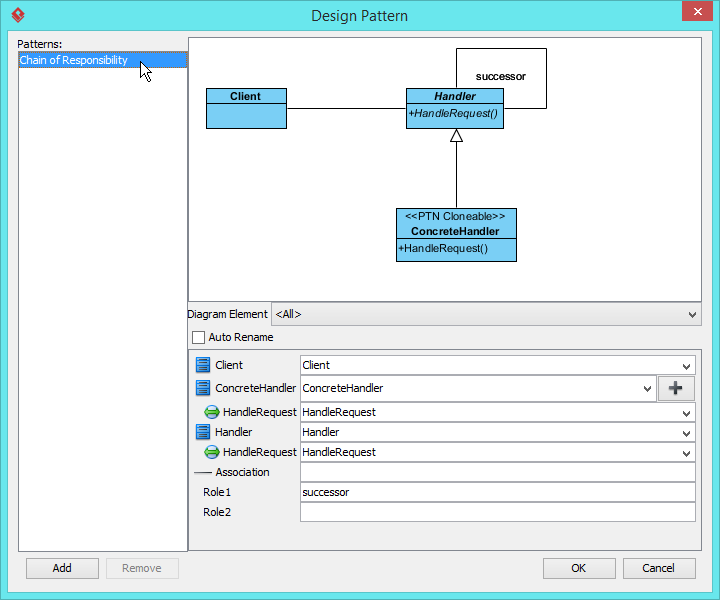
- In the Design Pattern dialog box, select Chain of Responsibility from the list of patterns.
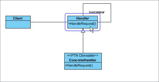
- Click on Handler in the overview.
- Rename Handler to CoinDispenser, and operation HandleRequest to Dispense at the bottom pane.

- Click on ConcreteHandler in overview, and rename it to DollarDispenser, and operation HandleRequest to Dispense.
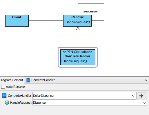
- We need one more concrete handler for dispensing cents. Keep ConcreteHandler selected, click on + and select Clone… from the popup menu.

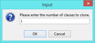
- Enter 1 to be the number of classes to clone. Click OK to confirm.
- Rename ConcreteHandler2 to CentDispenser, and operation HandleRequest to Dispense.

- Click OK to apply the pattern to diagram.
- Tidy up the diagram. Here is the result:
